Options
- Temperature program controller
- Multi functional unit
- Serial interface
- Vacuum pump stand for higher vacuum 10-2(3)
- Bottle pressure reducer
- Burning-off device with flame supervision
- Safety package
- Gas warning system
- Insulation for hydrogen operation H2
- Viewing glass
- Door guidance
- Furnace underframe
- Condensate trap
- Process guiding software
- Interface converter
- Programmable 1-channel line recorder
- Alsint 99,7-boxes
- Molybdenum heating elements
- Tungsten heating elements
- Switchover
PRODUCT SPECIFICATIONS
Sizes
| Model | Liter | T max in °C | Useful chamber mm (w x d x h) | kW |
|---|---|---|---|---|
| HT-1400-Vac | 4,0 | 1400 | 130 x 190 x 160 | 3,5 |
| HT-1400-M-Vac | 12,5 | 1400 | 250 x 200 x 250 | 6,0 |
| HT-1400-G-Vac | 26,0 | 1400 | 250 x 350 x 300 | 9,0 |
| HT-1400-GT-Vac | 52,5 | 1400 | 250 x 700 x 300 | 16,0 |
| HT-1600-Vac | 4,0 | 1600 | 130 x 190 x 160 | 3,5 |
| HT-1600-M-Vac | 12,5 | 1600 | 250 x 200 x 250 | 6,0 |
| HT-1600-G-Vac | 26,0 | 1600 | 250 x 350 x 300 | 9,0 |
| HT-1600-GT-Vac | 52,5 | 1600 | 250 x 700 x 300 | 16,0 |
| HT-1800-Vac | 4,0 | 1750 | 130 x 190 x 160 | 3,5 |
| HT-1800-M-Vac | 12,5 | 1750 | 250 x 200 x 250 | 6,0 |
| HT-1800-G-Vac | 26,0 | 1750 | 250 x 350 x 300 | 9,0 |
| HT-1800-GT-Vac | 52,5 | 1750 | 250 x 700 x 300 | 16,0 |
| HT-1800-Plus-Vac | 3,0 | 1750 | 110 x 170 x 160 | 5,0 |
| HT-1800-M-Plus-Vac | 9,5 | 1820 | 230 x 180 x 230 | 8,0 |
| HT-1800-G-Plus-Vac | 21,0 | 1820 | 230 x 330 x 280 | 12,0 |
| HT-1800-GT-Plus-Vac | 44,0 | 1820 | 230 x 680 x 280 | 21,0 |
| HT-1900-M-Vac | 8,0 | 1950 | 220 x 170 x 220 | 7,0 |
| HT-1900-G-Vac | 16,6 | 1950 | 220 x 280 x 270 | 12,0 |
| HT-1900-GT-Vac | 39,8 | 1950 | 220 x 670 x 270 | 16,0 |
Useful chamber decreases in case of H2-insulation.
Technical Data
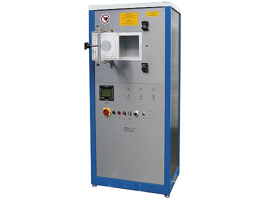
Furnace housing
The protective gas and vacuum tight inner housing which is reinforced on all sides is cooled by fans in order to avoid an outside wall temperature exceeding 180°C.
The correspondingly designed outside housing remains cold (max. 40°C above room temperature) except for the door front plate.
The correspondingly designed outside housing remains cold (max. 40 °C above room temperature), except for the door front panel. The vacuum tight swivelling door with silicone rubber sealing is constructed as explosion clap (pressure relief approximately 10 – 20 mbar) and equipped with turn-locks with adjustable spring pressure resistance.
On the rear side of the furnace, there are connection flanges for protective gas in- and outlet, vacuum and thermocouple.
The door flange, the connections for thermocouples and heating elements as well as the gas outlet are water cooled.
Insulation
The inner housing is covered with fiber boards respectively graphite felt. The use of these lightweight, low heat storing materials, enable extremely short heating up and cooling down cycles.
Heating
The furnace is heated by exchangeable MoSi2– bzw. Mo-, W- or graphite heating elements, which are operated via a three phase thyristor unit with phase angle firing and a transformer. The heating element connections are being led outside on the side.
Thermocouple
On the side, approximately in the middle of the furnace (installed from the back), a PtRh-Pt double thermocouple type S, B or a WRe-thermocouple type C (accuracy: class 2 according to DIN IEC part 2) measures the temperature. One pair of thermocouples is led to the temperature controller and one to the safety controller.
Switch and control unit
In a housing connected with the furnace part, basically the following components are installed:
- 1 lockable safety controller for additional protection of heating and insulation
- 1 three phase thyristor unit for phase angle firing
- 1 pre-transformer
- 1 operating hour counter
- 3 amperemeter
Gas/Vacuum unit (middle part of furnace housing)
The gas/vacuum unit contains a vacuum rotary vane pump, all necessary valves, underpressure switch and protective gas flowmeter. Vacuum and overpressure display are installed in the front plate. When using flammable, toxic or explosive protective gases, purging with Nitrogen has to be possible. Therefore, there are two gas lines with lock-off valves and needle dosing valves. Both gas lines are led together to one gas supply line in front of the furnace. The flowmeter with needle dosing valve is installed in the gas supply line. In the exhaust line, there is also a throttle valve which keeps the furnace inner pressure at max. 4-7 mbar in case of low gas throughput. All tube lines are made of copper. Bottles and pressure reducing valves with manometer for a max. outlet pressure of 200 mbar have to be provided by customer. In case of operation with reducing gases, a burning-off device (optionally) will be necessary.
When using protective gases, the heating element temperature in case of MoSi2-heating elements is limited according to below chart:
Atmosphere: max. Heating element temperature
- Dry hydrogen gas: 1150 °C
- Humid hydrogen gas, dew point + 15°C: 1450 °C
- Carbon monoxide: 1450 °C
- Cracked and partly burnt ammonia (app. 8% H2): 1400 °C
- Methane: 1350 °C
- Vacuum up to 10-1: 1350 °C
Above-mentioned chart only indicates values at optimum conditions which, from case to case, might have to be revised downwards respectively need a particular furnace run. Furnace temperatures are app. 30-100°C below heating element temperatures.
When using flammable, toxic and explosive protective gases, operator has to take care of safe and continuous purging of the furnace chamber.
In that case, we recommend supervision by our safety package (see options).
PRODUCT PROPERTIES
| Product Line: | type series |
|---|---|
| Operation Mode: | Batch |
| Construction Types: | Furnace |
| Designs: | Chamber furnace |
| Temperature Max (°C): | 1950 |
| Heatings: | electrical |
| Heatingmethods: | resistance |
| Atmospheres: | Air, Controlled gas atmosphere, Vacuum |
| Applications: | brazing, calcination, crystal growing, firing, gemstone heat treatment, melting, reduction, sintering |









Đánh giá
Chưa có đánh giá nào.