Options
- Serial interface RS 485
- Further program controller
- Screen recorder
- Useful chamber temperature 1400 °C (short time)
PRODUCT SPECIFICATIONS
Sizes
| Type | T. max. in °C | Liter | Useful chamber (w x d x h) | kW |
|---|---|---|---|---|
| KK-H 1000 L | 1280 | 1050 | 850 x 1450 x 840 | 70 |
| KK-H 2000 L | 1280 | 1850 | 850 x 1950 x 1120 | 120 |
| KK-H 3000 L | 1280 | 2750 | 850 x 2900 x 1120 | 160 |
| KK-H 1000 | 1340 | 1050 | 850 x 1450 x 840 | 70 |
| KK-H 2000 | 1340 | 1850 | 850 x 1950 x 1120 | 120 |
| KK-H 3000 | 1340 | 2750 | 850 x 2900 x 1120 | 160 |
Technical data
Furnace housing
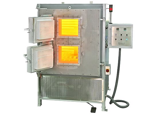
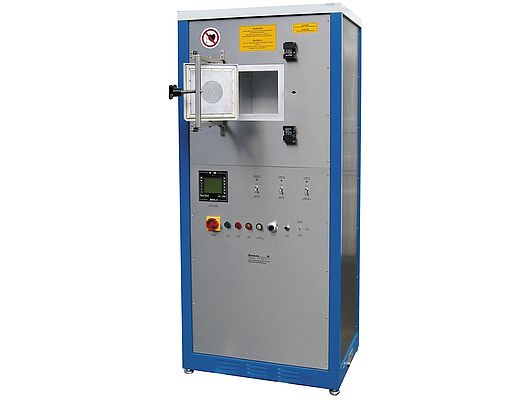
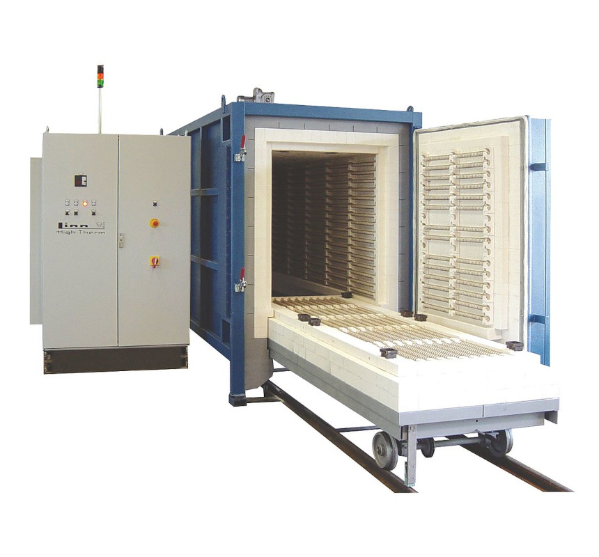
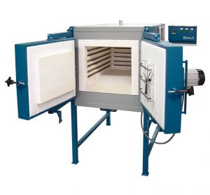
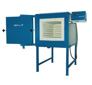
The furnace consists of a solid housing made of a profile steel/ steel sheet construction. The closing is effected by a swiveling door hinged to the left side (closing elements right). As protection against corrosion the housings are coated with high quality structural lacquer type 2-K. The furnace body is coated in blue and the cover sheet as well as the switch cabinet in white.
Insulation
The lining is effected according to the application as well as the maximum temperature and consists of high quality refractory light bricks and fibre insulation materials.
Heating
The heating spirals made of Kanthal A1 respectively APM heating wire on ceramic supporting tubes are located on three walls, in the door and in the furnace bottom for free radiation. Therewith an easy exchange of the spirals is guaranteed.
Shuttle kiln
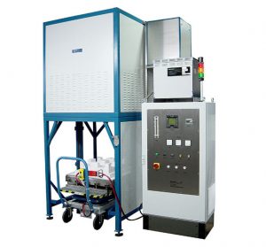
The furnace bottom is designed as shuttle covered with well thermal conductive plates and is moved tracklessly with a steering gear. Below the furnace guiding rails are placed which ease the drive in of the shuttle. The shuttle is provided with high quality heavy duty steering wheel – and rack wheels. For heavy components the shuttle should be provided with supporting grids (option).
Inlet air regulator/ exhaust flaps
For the activation of the waste of the burning materials and the cooling behaviour during cooling phase air channels are installed into the furnace bottom through which fresh air with well chamber distribution will be guided to the top side due to thermal lifting. The discharge of waste air is made by two discharge vents (di 80 mm) in the cover and can be regulated manually by flaps. The forwarding of the waste air into the customer – provided waste system is not included in the scope of delivery.
Switch and control unit
The control unit is located in a separate switch cabinet that is connected to the furnace via 1,8 m flexible lines. This cabinet contains next to all components being necessary for operation the below described program controller G800:
- 2 or 3 setpoint controller with PID behaviour
- logic output and stepless output
- max. 4 programmes on max. 16 segments/ steps programmable
- display of actual and desired value
- self-optimization prevents overshooting
- separation of control level and configuration level
- 4 switchable parameter sets
- alarm signal in case of thermocouple fracture
- serial interface RS 485 as an option
For the temperature control PtRh-Pt thermocouples type „S“ (accuracy class 2 according to DIN IEC 584 part 2) are used. For furnace protection an internal temperature monitor is used.
When opening the furnace door a safety switch switches off the furnace and after closing the furnace will switch on again.
PRODUCT PROPERTIES
| Product Line: | type series |
|---|---|
| Operation Mode: | Batch |
| Construction Types: | Furnace |
| Designs: | Boogie hearth furnace, Chamber furnace |
| Temperature Max (°C): | 1340 |
| Heatings: | electrical |
| Heatingmethods: | resistance |
| Atmospheres: | Air |
| Applications: | calcination, firing, oxydation, pre-heating, shrink fitting, sintering, stress-relieving, tempering |






Đánh giá
Chưa có đánh giá nào.